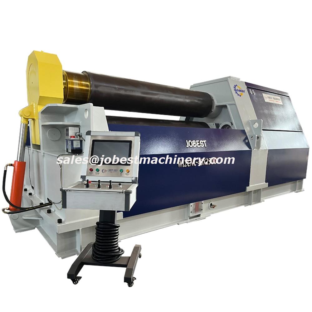
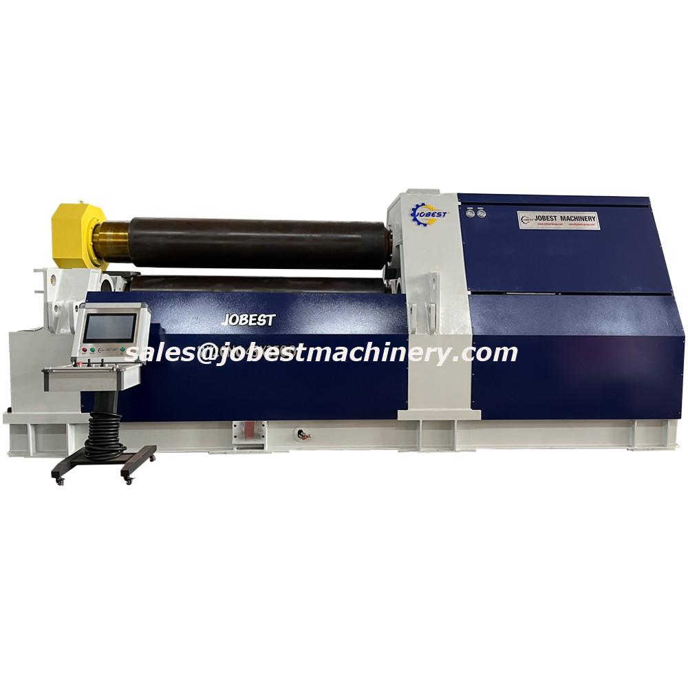
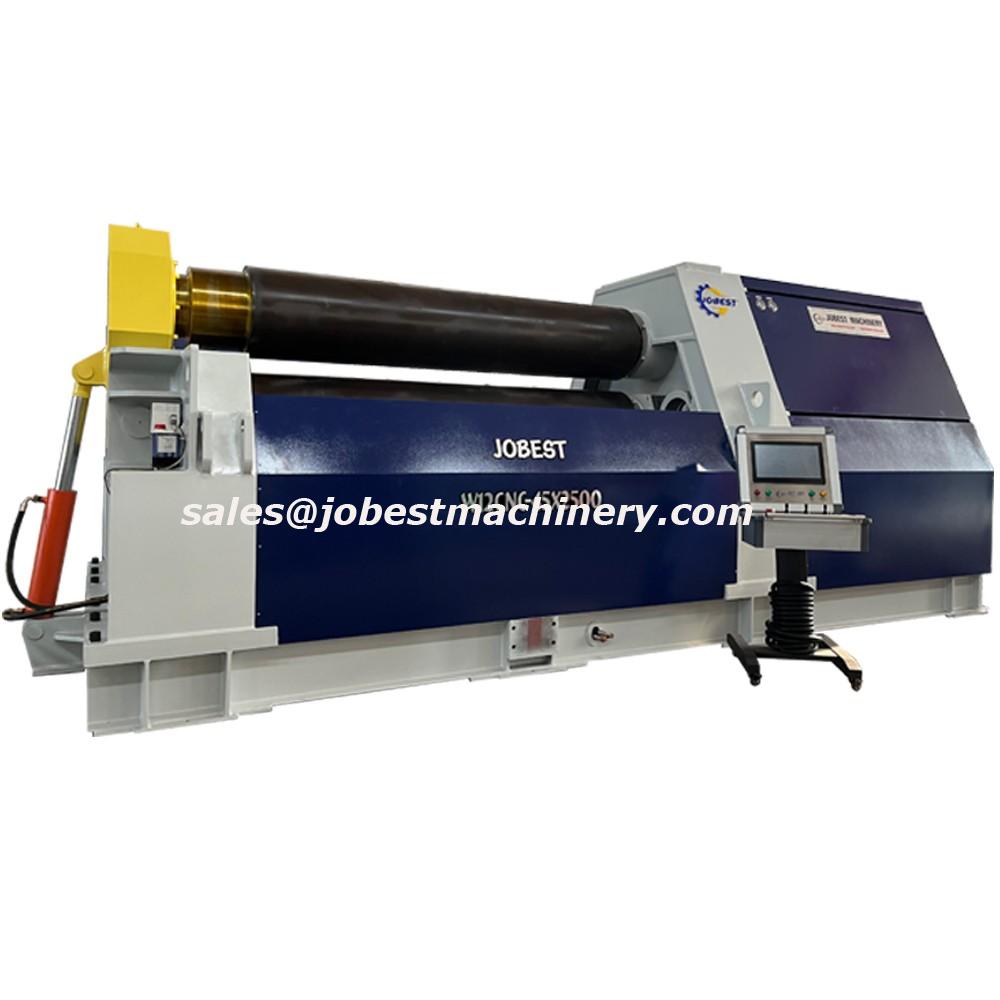
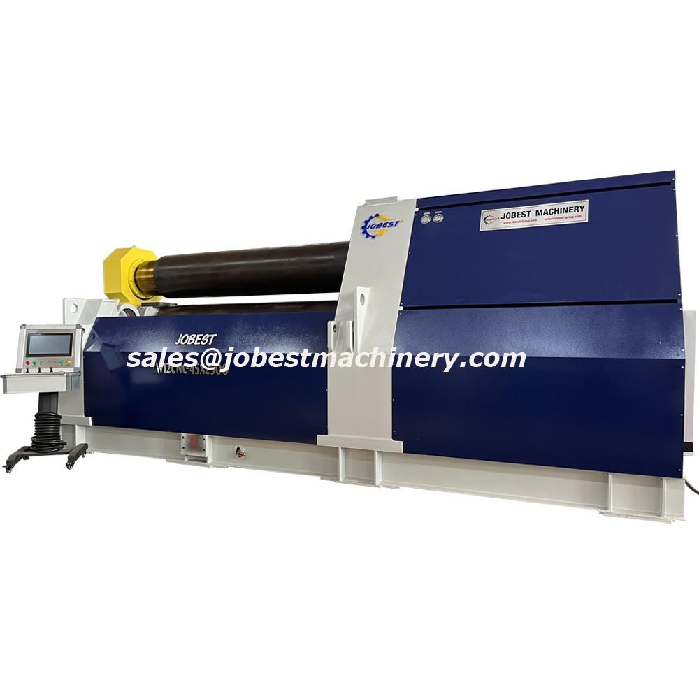
Plate Rolling Machine
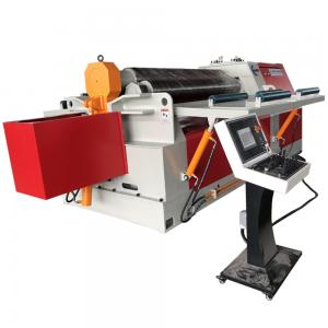
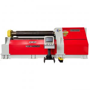
This four roll plate bending rolls are recognized worldwide as the fastest, safest, most precise and easy to use plate roll available in the all range.
This is a fully hydraulic 4-roll bending machine with pre-bending. Rolls length up to 6.000mm, plate thickness up to 150 mm
This Advanced Design Has The Following Benefits Such As:
(1) Plate is introduced horizontally (and not tilted as on the three roll double pinch)
(2) Plate is squared instantly against the back roll (reducing risk of a mis-matched end condition of the part)
(3) Requires space only on one side of the machine, where the plate is introduced to the machine
(4) Greatly reduced flat-end (due to better pre-bending) thanks to the clamping roll that can take the edge to the precise tangent points of the top and bottom rolls
(5) It is the fastest machine to roll a can, as it would require only one position for each side bending roll
(6) The entire cylinder can be finished in only one pass (within a suitable capacity), including pre-bending of the edges
No need to pre-bend both ends before starting to roll the entire cylinder, as required with a 3 roll
No need to remove, turn and re-insert the plate as on a 3 roll single pinch
(7) The four roll could be even 50-80% faster and more productive than any style three roll
(8) The most suitable for CNC operation, as the plate is under a better control, clamped between the top and bottom rolls, until the part is finished
The Four Roll Design Is Recommend For Clients Who:
1. Wish to operate through CNC, with less dependence on operator skills
2. Look for more steady quality of the rolled products.
3. Look for high productivity, and increased profits.
4. Require good accuracy and quality improvements.
5. Need handling equipment for larger plates, who are also concerned for production or safety reasons.
6. Are new to plate rolling, as it is the easiest plate roll to operate.
Rolling Process:
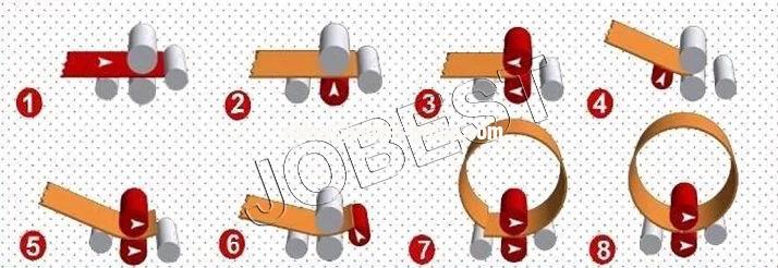
1. Plate alignment and squaring positively against the back roll.
2. Plate pinching (at a pre-set, safe, pressure).
3. Plate is moved as far back as possible between the top and bottom rolls, for the very minimal flat-end.
4. Side roll is moved up, to bend the edge of the plate (pre-bending position).
5. The rolls rotate, to feed the plate, to round the entire leading edge.
6. Inversing the side rolls (down the front roll; up the rear roll).
7. Rotate the rolls, feeding the plate to roll the entire plate length to the required diameter.
8. Pre-bending the trailing edge is an automatic end-of-process feature, continuing feeding the plate forward.
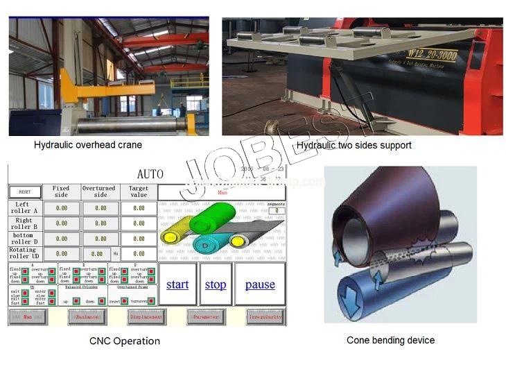
Optional Components:
Product Parameters
| Specification | Max roll thickness(mm) | Max roll width (mm) | Yield strength (Mpa) | Roll speed (m/min) | Min roll diameter (mm) | Diameter of upper roller (mm) | Diameter of down roller (mm) | Diameter of side roler (mm) | Motor (kw) |
| W12CNC-6X2000 | 6 | 2000 | 245 | 4.5 | 350 | 190 | 180 | 150 | 4 |
| W12CNC-6X2500 | 6 | 2500 | 245 | 4.5 | 400 | 210 | 200 | 170 | 5.5 |
| W12CNC-8X2000 | 8 | 2000 | 245 | 4.5 | 400 | 210 | 200 | 170 | 5.5 |
| W12CNC-8X2500 | 8 | 2500 | 245 | 4.5 | 480 | 230 | 210 | 190 | 7.5 |
| W12CNC-10X2000 | 10 | 2000 | 245 | 4.5 | 480 | 230 | 210 | 190 | 7.5 |
| W12CNC-10X2500 | 10 | 2500 | 245 | 4 | 500 | 250 | 230 | 210 | 11 |
| W12CNC-12X2000 | 12 | 2000 | 245 | 4 | 500 | 250 | 230 | 210 | 11 |
| W12CNC-12X2500 | 12 | 2500 | 245 | 4 | 550 | 270 | 250 | 230 | 11 |
| W12CNC-16X2500 | 16 | 2500 | 245 | 4 | 600 | 310 | 290 | 250 | 15 |
| W12CNC-20X2000 | 20 | 2000 | 245 | 4 | 600 | 310 | 290 | 250 | 15 |
| W12CNC-16X3200 | 16 | 3200 | 245 | 4 | 600 | 310 | 290 | 250 | 15 |
| W12CNC-12X4000 | 12 | 4000 | 245 | 4 | 600 | 310 | 290 | 250 | 15 |
| W12CNC-25X2000 | 25 | 2000 | 245 | 4 | 800 | 350 | 320 | 240 | 22 |
| W12CNC-20X2500 | 20 | 2500 | 245 | 4 | 640 | 350 | 320 | 240 | 30 |
| W12CNC-30X2000 | 30 | 2000 | 245 | 4 | 1000 | 400 | 360 | 240 | 37 |
| W12CNC-25x2500 | 25 | 2500 | 245 | 4 | 800 | 400 | 360 | 240 | 37 |
| W12CNC-35x2000 | 35 | 2000 | 245 | 4 | 1200 | 420 | 380 | 210 | 37 |
| W12CNC-30X2500 | 30 | 2500 | 245 | 4 | 1000 | 400 | 360 | 230 | 37 |
| W12CNC-40X2000 | 40 | 2000 | 245 | 4 | 1400 | 480 | 400 | 420 | 45 |
| W12CNC-45X2000 | 45 | 2000 | 245 | 3.5 | 1600 | 500 | 450 | 380 | 45 |
| W12CNC-35X2500 | 35 | 2500 | 245 | 3.5 | 1200 | 480 | 400 | 420 | 45 |
| W12CNC-40X2500 | 40 | 2500 | 245 | 3.5 | 1400 | 500 | 450 | 380 | 45 |
| W12CNC-45X2500 | 45 | 2500 | 245 | 3.5 | 1600 | 530 | 480 | 450 | 63 |
| W12CNC-35X3000 | 35 | 3000 | 245 | 3.5 | 1200 | 500 | 450 | 380 | 45 |
| W12CNC-45X3000 | 45 | 3000 | 245 | 3.5 | 1600 | 560 | 500 | 450 | 63 |
| W12CNC-55X2500 | 55 | 2500 | 245 | 3.5 | 2000 | 600 | 550 | 500 | 75 |
| W12CNC-55X3000 | 55 | 3000 | 245 | 3.5 | 2000 | 620 | 560 | 500 | 75 |
| W12CNC-65X3000 | 65 | 3000 | 245 | 3 | 2400 | 670 | 600 | 550 | 110 |
JOBEST MACHINERY: BEST-QUALITY, BEST-SERVICE, BEST-PRICE!!! SEND INQUIRY
SEND US INQUIRY , GET VALID QUOTATION AND NEWEST CATALOG !
 JOBEST MACHINERY TECHNOLOGY